4 Wire Strobe Light Wiring Diagram Collection
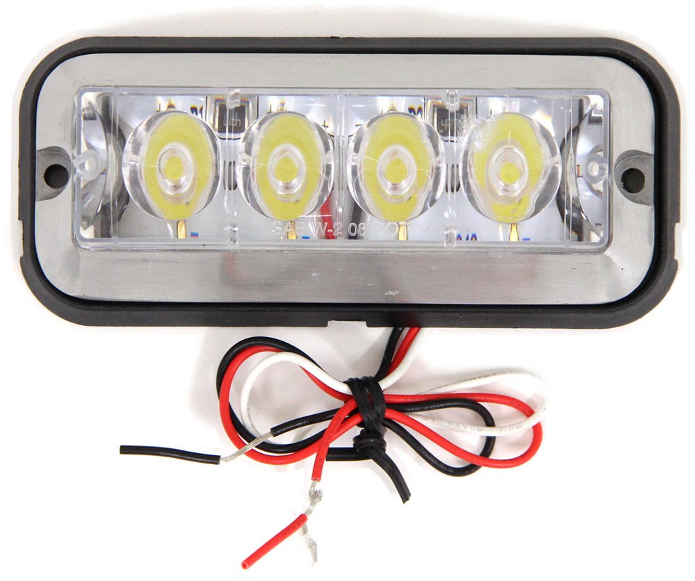
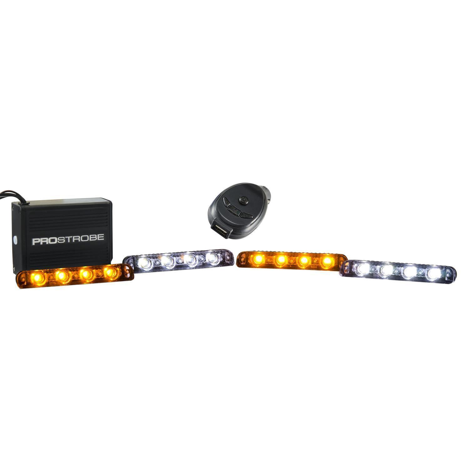
4Pcs LED Flash Strobe light 12LED Super Bright Stroboscope Auto LED Car
With a 4 wire strobe light wiring diagram, the gauge of wire should be specifically addressed. SYNC-capable LED lightheads can be SYNCed to a SYNC-capable strobe power supply. (such as the CSS or UPS64LXA) by wiring their GREY wires together. Use a splicer with a gauge that fits over the wire you want to tap.
4 wire strobe light wiring diagram DeveronMekseb
A 4 wire strobe light wiring diagram is a diagram that shows the electrical connections and wiring of the components of the strobe light system. It typically includes a wiring diagram for the transformer and the light fixtures. It also includes wiring diagrams for connecting the components to the power source and to each other.
Whip Light Wiring Diagram
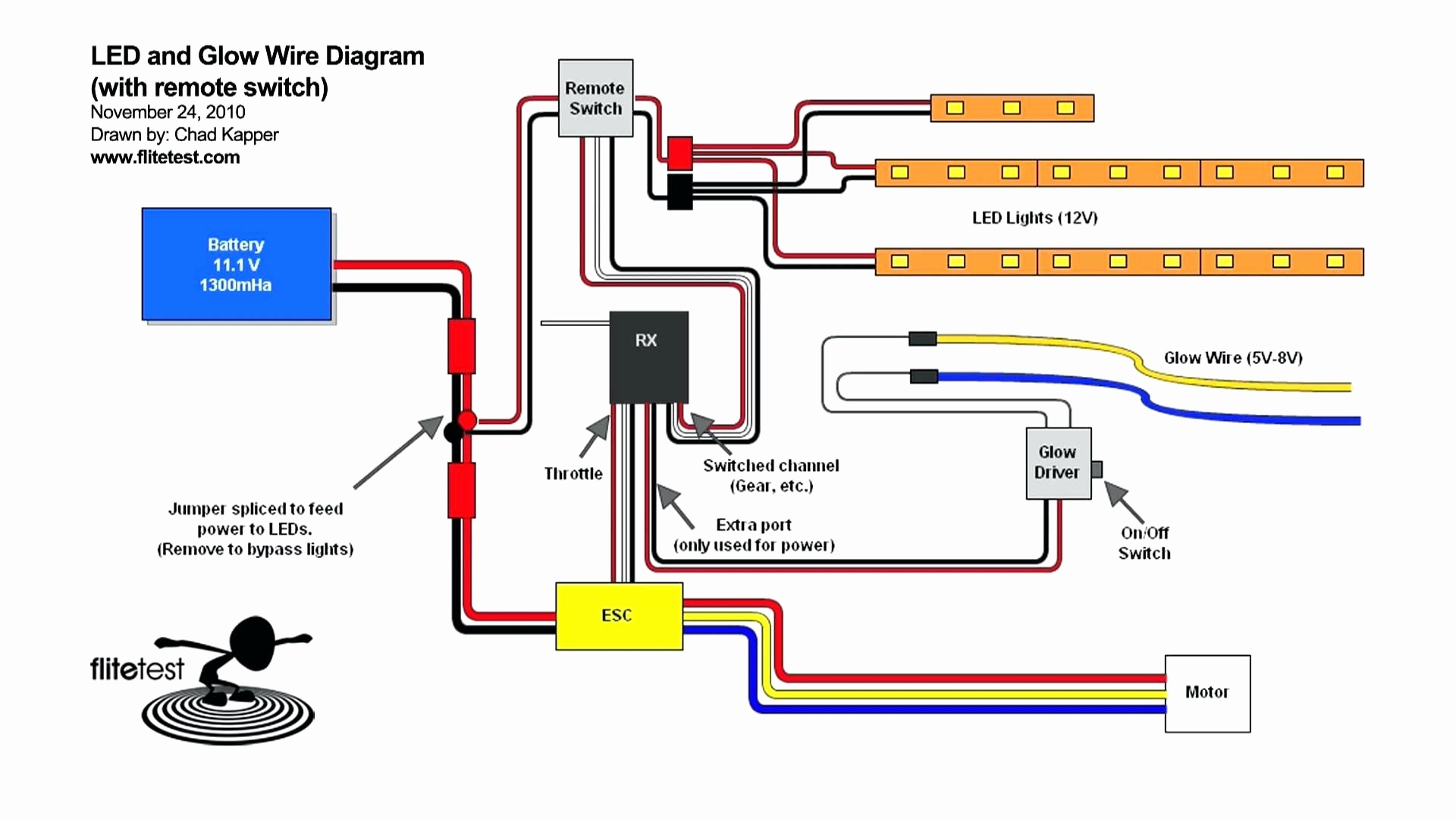
Grote's Answer Grote's 7679x Auxiliary LED Strobe Lights - wiring and flash patterns: Red: To +VDC (fuse@ 3A) Black: To Chassis Ground White: For steady burn, apply +VDC Yellow: For Synchronization - Connect yellow wires of all heads together for synchronization (all heads must be set at the same pattern) For Simultaneous or Alternating Flash:
3 wire led strobe light wiring diagram
tion appliances. Horn/strobe products are available in two versions. The 2-wire products fit systems where a single NAC controls both horn and strobe. The 4-wire products are intended for systems which have sepa-rate wiring circuits for the horn and strobe. All SpectrAlert Advance prod-ucts are suitable for use in synchronized systems.

4 Wire Strobe Light Wiring Diagram Wiring Diagram
4 wire strobe light wiring requires the use of a four-wire connector, or "C" connector, which is commonly available from most hardware stores. This connector consists of two neutral wires, two positive wires, and one common ground wire.. On Off Switch Led Rocker Wiring Diagrams Oznium.

4 Wire Strobe Light Wiring Diagram Collection
By John Peter | December 27, 2022 0 Comment Four-wire strobe lights are an incredibly versatile and effective way to illuminate any space. Whether you're looking for aesthetically pleasing lighting for a home or for a commercial setting, four-wire strobe lights have a lot of advantages that make them a great choice.

Fire Alarm Strobe Light Wiring Diagram Gosaga
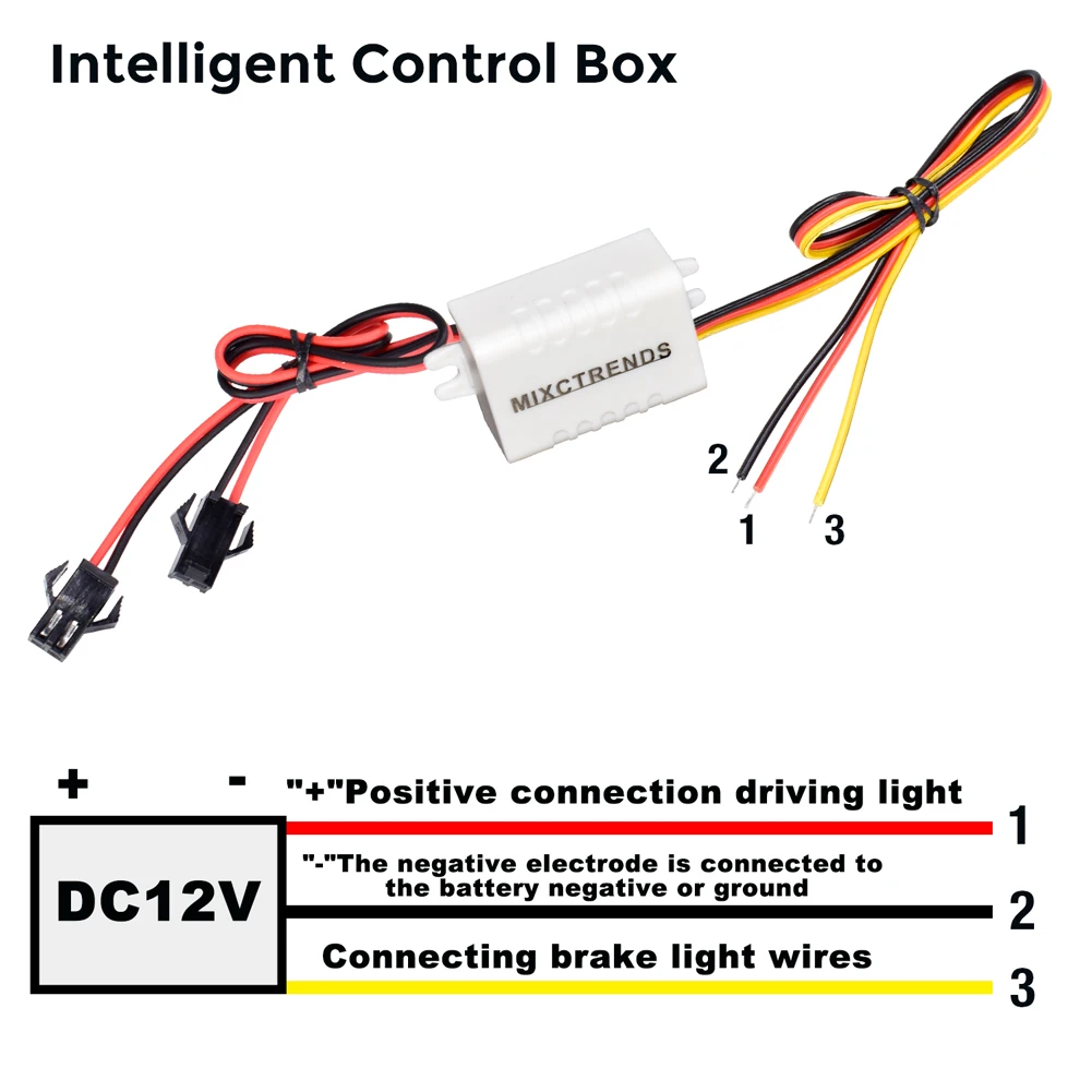
red wire connects to positive and the black wire connects to negative. If the connections are reversed, the light will not function. Use 18-gauge wire for runs under 20-feet. For wire runs over 20-feet, consult local electrical codes. Ensure that the vehicle's supply voltage is within the voltage rating specified on the strobe light.

4 Wire Strobe Light Wiring Diagram diagramwirings
Is the switch lighted? If yes, then one of the pins is ground and you'll have to figure out which one. If no, then it means the switch is more than just on/off and you'll have to figure out what kind of switch you have (such as on-off-on) Pictures of the switch front and back might help I just like to argue B B-love508 Discussion starter

4 Wire Strobe Light Wiring Diagram Collection
4 wire strobe light wiring diagram In the world of electrical circuits, the concept of wiring diagrams is as fascinating as it sounds. Today, we delve into the enchanting realm of 4-wire strobe light wiring diagrams. Unlocking the mysteries behind these diagrams is like deciphering the secret message of an ancient civilization. So, gear up as we embark on a journey to unravel the intricacies.
4 Wire Strobe Light Wiring Diagram Collection
Our 4-wire horn strobes come with 10 field selectable tone and volume combinations and 7 field selectable candela settings. Intended for indoor applications and approved for ceiling mount installations. 4-wire horn strobes and strobes are public mode notificati2on appliances in-tended to alert occupants of a life safety event.

3 Wire Strobe Light Wiring Diagram
Push the defective strobe tube assembly out of the reflector. Disconnect the red 3-position connector at the end of the tube's wiring. To facilitate assembly, apply a high temperature grease, or Vaseline, to the rubber edge of the strobe tube. SLOWLY insert the strobe tube into the reflector housing.
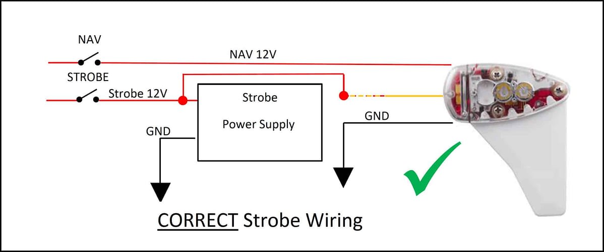
Strobe Wiring Configuration uAvionix
4 Wire Synch Wiring Diagram CA 7082A Red: Anode , Live, Power Green: Changing Flash Patterns White: Synchronisation Black : Earth, Negative Pole Light 1 Light 2 Light 3 Light 4 - S Sync Settings: + - S + - S 12/24 V + Power Switch - S + Pattern Switch

whelen led light bar wiring diagram
3. Find the 12 position pin connector (SC) and the 8 position socket connector (PSC) coming from the main harness and plug them into the power supply as shown. 4. Plug the 4 lightheads into their 3 position Amp connectors as you install them into their positions in the lightbar along with the existing options you removed.
4 Wire Strobe Light Wiring Diagram Collection
The Knapheide Strobe Light Wiring Diagram is an invaluable tool for anyone working on a vehicle's lighting system. It provides a comprehensive look at all of the wiring that goes into a typical strobe light system and can be used to diagnose and repair problems. If you're a DIYer, the Knapheide Strobe Light Wiring Diagram is essential.For.

5 Wire Strobe Light Wiring Diagram
Strobe Light Circuit. In this project let us develop an LED Strobe light circuit using the popular 555 timer IC. A strobe light or a stroboscopic lamp is one which can produce regular flashes of light. We are designing this circuit using a 555 timer for setting the delay between each flash and a high power LED light as the source of light.
32 Strobe Light Wiring Diagram Wiring Diagram Niche
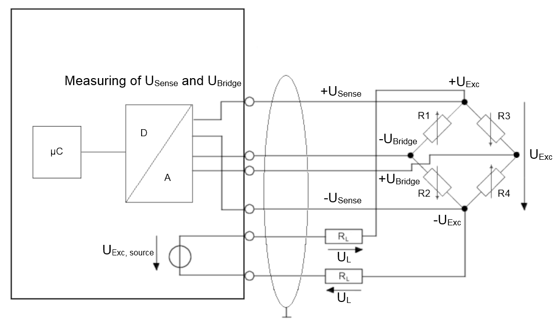
In a 4 wire strobe light wiring diagram, these symbols are used to help identify the various components and the power source that they are connected to. Knowing the meaning of these symbols will help you understand the wiring diagram better and make sure that you have all the right components connected in the right way. Wire Gauges and Connectors
